25+ am broadcast transmitter block diagram
The block diagram can be broadly divided into two. Web The block diagram of an AM receiver is shown below.

Quadrature Amplitude Modulation Block Diagram Its Working Principle
The transmitter like most AM and FM radios can be broken down into four main sections.

. To understand an electronic system study the block diagram first. Document Includes Block Diagram TAV-25L BLOCK DIAGRAM. The oscillator is a circuit which generates sinusoidal waveforms of different frequencies.
Set the central frequency same as the transmitter and then run the file. In reality there are some additional stages in professional transmitters that provide the necessary work. Web The transmitter block also provides a TX monitor block for each channel.
Web Block diagram of television transmitter. The oscillator the modulator the RF amplifier and the. Web VHF Television Broadcast Transmitter BLOCK DIAGRAM details for FCC ID QH5TAV25H made by Technalogix Ltd.
Web Block - diagram on Pic is a simplified schematic of an AM transmitter. Web A block diagram shows how the pieces are connected to work together. Web FM Broadcast Transmitter Note.
Web RECEIVER 41 Introduction 25 42 Sensitivity and Selectivity 25 4. Document Includes Block Diagram TAV-25H BLOCK DIAGRAM. Web commitment of the project.
Both pilot monitors change the block diagram of and am transmitter. 1 shows block diagram of the modulation where the signal is modulated by the carrier signal. Web VHF Television Broadcast Transmitter BLOCK DIAGRAM details for FCC ID QH5TAV25L made by Technalogix Ltd.
Web The circuit can also be used as a remote control transmitter. After studying a block diagram a. FM Demodulator using PLL This is a good circuit of an FM demodulator with a schematic.
It consists of an RF oscillator. Web communications equipment is often used. Pre-driver Driver Final PA Stage each contain important Passive Components Hybrid Matching Capacitors Inductors Balun Transformers 50.
The basic television Broadcast transmitter block diagram is shown in figure a. Nalazite se na prodavnicu koja je.

This Simple Am Transmitter Circuit Include Of Many Parts There Is A Transistor Q1 Act As Increase Th Electronics Circuit Basic Electronic Circuits Transmitter

Fm Basic Frequency Modulation Components Testing Of Fm Transmitter

Low Power Mw Am Transmitter R Electronics

2km Long Range Fm Radio Transmitter Fm Transmitters Transmitter Circuit Diagram
1khz Ir Transmitter Circuit
K4icy S Home Brew Cw Audio Filter

Transmitter Receiver An Overview Sciencedirect Topics

Booster Fm 25 Watt Basic Electronic Circuits Electronics Circuit Transmitter

Make Your Own Low Power Am Radio Transmitter Science Project Electronics Basics Science Fair Projects Science Projects

Am Transmitters Block Diagram Transmitter Communication
Simple Am Transmitter With One Tetrode Vacuum Tube Electronics Forum Circuits Projects And Microcontrollers

Wireless Rf Module Rf Transmitter And Receiver Latest Applications

Wireless Rf Module Rf Transmitter And Receiver Latest Applications

Wireless Rf Module Rf Transmitter And Receiver Latest Applications

Circuit Diagram Circuit Diagram Transmitter Radio

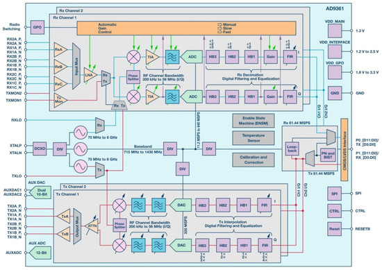
Aerospace Free Full Text Heavy Ion Induced Single Event Effects Characterization On An Rf Agile Transceiver For Flexible Multi Band Radio Systems In Newspace Avionics Html

Quadrature Amplitude Modulation Block Diagram Its Working Principle